
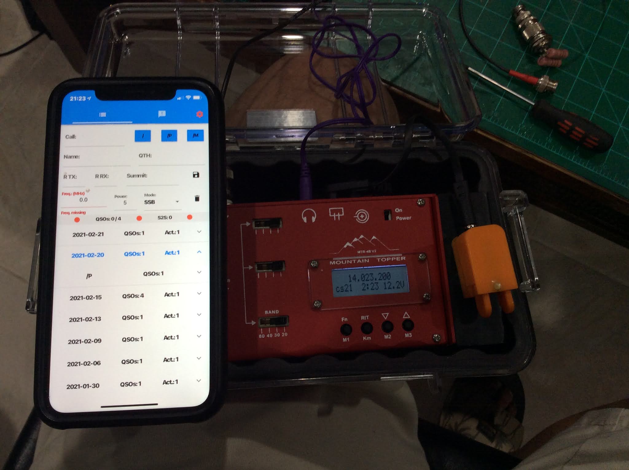
Below: the phone is attached to the QuadLock while the GM0EUL key is fastened via its magnetic base. The radio can be used without taking it out of the Pelican case. The phone is running the OutdLog app for iOS for logging in contacts.
Below: the phone is attached to the QuadLock while the GM0EUL key is fastened via its magnetic base. The radio can be used without taking it out of the Pelican case. The phone is running the OutdLog app for iOS for logging in contacts.
The setup is as shown in the image below. The two antennas are arranged as inverted Vee in the same azimuthal orientation with the feedpoint on the south side denoted by the blue boxes. The image shows 10 foot topographic contours and also shows the global imagery to show both the presence of roads and vegetation. The two antennas are separated by about 75 feet of space. The NY4G coupler has the 2 turns primary and 14 turns secondary with the crossover and bifilar winding of the primary. The VY2AJ coupler has the 3 turns primary, 24 turns secondary with a tap instead of the bifilar winding and the turns are wound tightly together with no crossover. Both transmitters are identical 200 milliwatts WSPRlite programmed with their respective call signs. The only variables are the couplers and the relative position of the antennas with each other. They both see the same instantaneous propagation conditions.

During the first day - NY4G was in the position of VY2AJ and vice versa. During the second day, the positions were swapped to correspond to the image above. The results from the first day below:


NY4G is at this lower position. If one deducts the 800 km advantage from the previous two days results to sort of “equalize” matters from the “advantaged position” then
the average distance for Day 1 - reported by DX10 Table with adjustment
Coupler 1 VY2AJ (3 turn primary) - 5649 km Position 1
Coupler 2 NY4G (2 turn primary) -4751 km Position 2
the average distance for Day 2 - with adjustment
Coupler 1 VY2AJ (3 turn primary) - 10080 km Position 2
Coupler 2 NY4G (2 turn primary) -5509 km Position 1
the average distance for Day 3 - data reported by DXeplorer
Coupler 1 VY2AJ (3 turn primary) - 9047 km Position 1
Coupler 2 NY4G (3 turn primary) -9797 km Position 2
This suggests that the advantage of the more efficient coupler in terms of distance ratio is somewhere between 20% to 80% better reach.
Stay tuned for similar tests on the lower bands.
https://owenduffy.net/blog/?p=12642
I wanted to record the URL for this important blog article by Owen Duffy on autotransformer
Measurements of the efficiency of the transformer cores have been made using the NanoVNA H4.
The results are documented here:
https://www.dropbox.com/sh/y4mb9xnwbn70hll/AACghPO0l2TF4UOuJAwyAGv6a?dl=0
The URL is ny4gefhw.com
Please take a tour and browse around.
The thirty meter band is such a "money band" for SOTA activations that it simply can't be ignored. Traditional end fed half waves either ignore it or put in a link to enable that band - e.g. the EndFedZ MountainTopper by LNR Precision (now Vibroplex).
It is possible to configure an end fed wire with two traps, one for 20m and the other for 30m. When finished, the inductive loading of the two traps shortens the antenna from 66 feet to 58 feet. The bandwidth for 20m covers the entire band. The band width for 40m is reduced but still perfectly acceptable within the CW portion of the band. There are losses associated with this trap - the combined losses from both traps is somewhere between 0.3 and 0.7 dB.
I used it during my activation of Grassy Ridge Bald W4C/EM-001 as documented by this YouTube video and it worked fantastically well with my LNR MTR4Bv2 and GM0EUL paddle.
Here is an image of the end fed half wave antenna. Only one trap is visible.

I was just going through reflection loss calculations and comparing efficient and inefficient transformers.
On 60m, inefficient transformer are only 58% efficient. Even with low SWR - say 1.5:1, the full entitlement available radiated power is only 2.78 watts.
Compare that with an efficient transformer at 83% efficiency - radiating into an SWR of 6 but matched with an ATU, the radiated power is 3.77 watts. Full entitlement with no coax losses is 4.15. one would not want to go through this exercise with an RG174 feedline as the coax losses are worse - available output down to about 2.3 watts. With very low SWR say 1.2, you are almost at full entitlement even with RG174.
So the lesson learned is - have a resonant antenna, however, in the case of mismatched antenna use the RG8X feedline instead of the RG174 and it always beats the inefficient transformer.
Having said all that, all this efficiency talk can be dominated by antenna configuration for an intended purpose. Let's say the intended purpose is to work close in chasers on 60m. An inverted V with an Apex at 20 feet has close to a 4 dBi at a high take-off angle as opposed to the same end fed wire set up as a vertical (as impractical as that may seem). The vertical will have a null at the high takeoff angle. So an efficient transformer even with low SWR will not work any stations and that inefficient transformer will work those close in stations all day long. There are a lot of factors that have to be optimized for effective antennas and as always - it always pays to begin with the end in mind and work backwards. What is the purpose, configure the antenna for that purpose and optimal gain, and then worry about SWR second and last transformer efficiency. It isn't easy. As often, summit conditions dictate antenna configuration - presence or non-presence of supports and it becomes a "one size fits all" or "one antenna configuration fits all" proposition - the ubiquitous inverted V.