
The objective of this project is to create a Hexbeam that can be put up anywhere and at any time. The mission objectives are
(1) A system for portable use - speed of put up and take-down are of the essence (less than 30 minutes)
(2) A system for temporary home installation for a situation with C&CR or HOA restrictions
(3) As light a weight as possible for the beam components
To meet these requirements, I used the instructions laid out by Leo Shoemaker K4KIO with the following modifications:
(a) the support cords are only 126 inches long instead of 128 which makes for a slightly more compact antenna system - this is facilitated by using insulated wire per Leo's dimensions for wire lengths. The support lengths are mathematically 126 inches.
(b) the base plate is made of plastic (UHMW) instead of aluminum to save weight. The plastic base plate use large "lightening holes" to save even more weight
(c) spreader arms use crappie fishing poles instead of fiberglass to save weight
(d) spreaders are permanently attached to the baseplate to speed up installation. The spreaders are folded in the upright position for storage or to get out of the way of obstructions - roof lines, house etc while assembling the wires.
(e) I only built it for the following bands - 20, 17, 15, 12 and 10.
Photo #1 - Hex-beam in the air over my deck. Support plate is at 35 feet above ground. Plate is guyed at the top level. The beam clears the roof by about 6 feet.
There is a proximity effect to the roof line - here is the data - the first column is bearing and the second column is SWR as measured using the K2 SWR bridge.
Bearing SWR
180 1.7
245 1.7
285 1.4
315 1.2
360 1.2
45 1.2
75 1.2
105 1.3
135 1.4
165 1.5

Photo #2 - Mast holder and rotator. Bearing blocks are UHMW plastic. Mast are 8 foot sections of Fiberglass mast from Max Gain Systems. The bottom of the mast is 7 feet high.
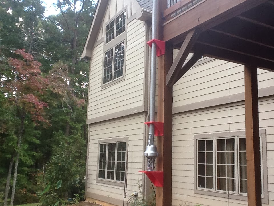
Photo #3 - Rotator controller sitting above the tuner

Photo #4 - Assembly of the hexbeam is done at deck level on a 9 foot wide deck with a 10 foot radius hex beam - the spreader folds up out of the way of the house until raised to full height as shown below

Photo #5 - Used in a portable operation - beam antenna mounted on a truck mounted mast holder. The one shown below was deployed on the Blue Ridge Parkway at an elevation of 4000 feet.

Photo #6 - Improvement to the baseplate - notice the inserts (black wedges to ensure the spreader take off angle is just right.

Photo #7 - Another photo as viewed from the side - Bearing blocks at three places


Photo #9 - Measured SWR - 20m band using AA-200 Analyzer

What is the source of plastic bearing blocks for the mast and base plate of the Hex?
ReplyDelete